|
(十三)——导航与定位框架 导航与定位是机器人研究中的重要部分。
一般机器人在陌生的环境下需要使用激光传感器(或者深度传感器转换成激光数据),先进行地图建模,然后在根据建立的地图进行导航、定位。在ROS中也有很多完善的包可以直接使用。
在ROS中,进行导航需要使用到的三个包是:
(1) move_base:根据参照的消息进行路径规划,使移动机器人到达指定的位置;
(2) gmapping:根据激光数据(或者深度数据模拟的激光数据)建立地图;
(3) amcl:根据已经有的地图进行定位。
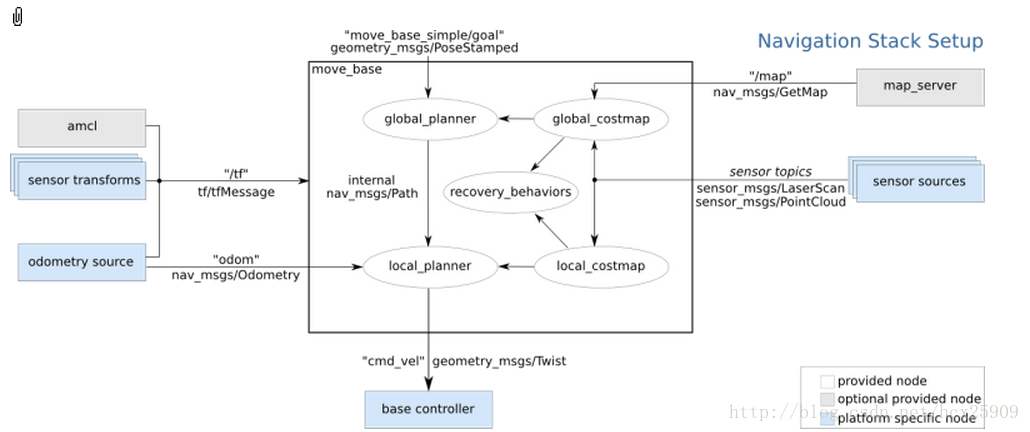
整体导航包的格局如下图所示:
其中白色框内的是ROS已经为我们准备好的必须使用的组件,灰色框内的是ROS中可选的组件,蓝色的是用户需要提供的机器人平台上的组件。
1、sensor transforms
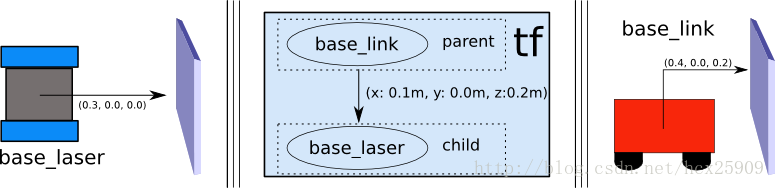
其中涉及到使用tf进行传感器坐标的转换,因为我们使用的机器人的控制中心不一定是在传感器上,所以要把传感器的数据转换成在控制中心上的坐标信息。如下图所示,传感器获取的数据是在base_laser的坐标系统中的,但是我们控制的时候是以base_link为中心,所以要根据两者的位置关心进行坐标的变换。
变换的过程不需要我们自己处理,只需要将base_laser和base_link两者之间的位置关系告诉tf,就可以自动转换了。
2、sensor sources
这里是机器人导航传感器数据输入,一般只有两种:
(1) 激光传感器数据
(2) 点云数据
具体实现见:http://www./wiki/navigation/Tutorials/RobotSetup/Sensors
3、odometry source
机器人的导航需要输入里程计的数据(tf,nav_msgs/Odometry_message),具体实现见:
http://www./wiki/navigation/Tutorials/RobotSetup/Odom
4、base controller
在导航过程中,该部分负责将之前得出来的数据转封装成具体的线速度和转向角度信息(Twist),并且发布给硬件平台。
5、map_server
在导航过程中,地图并不是必须的,此时相当于是在一个无限大的空地上进行导航,并没有任何障碍物。但是考虑到实际情况,在我们使用导航的过程中还是要一个地图的。
具体实现见:http://www./wiki/slam_gmapping/Tutorials/MappingFromLoggedData
在ROS的导航中,costmap_2d这个包主要负责根据传感器的信息建立和更新二维或三维的地图。ROS的地图(costmap)采用网格(grid)的形式,每个网格的值从0~255,分为三种状态:占用(有障碍物)、无用(空闲的)、未知。具体状态和值的对应关系如下:
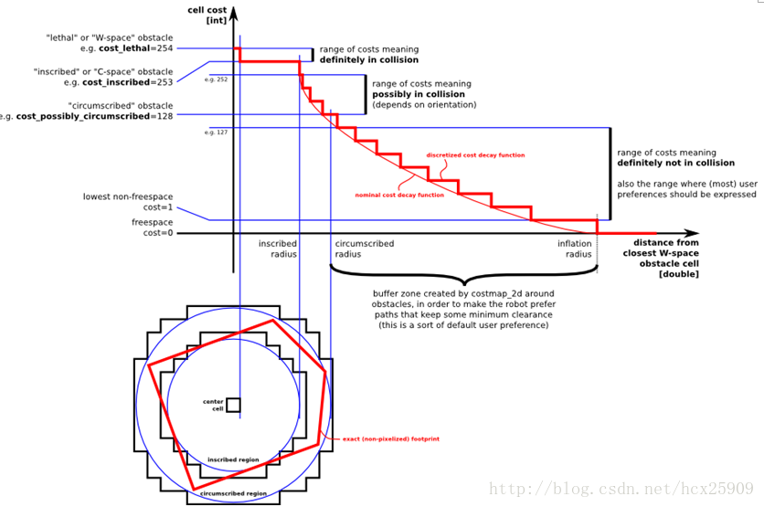
上图共分为五个部分:(下面的红色框图是机器人的轮廓,旁边的黑框是上图的映射位置)
(1) Lethal(致命的):机器人的中心与该网格的中心重合,此时机器人必然与障碍物冲突。
(2) Inscribed(内切):网格的外切圆与机器人的轮廓内切,此时机器人也必然与障碍物冲突。
(3) Possibly circumscribed(外切):网格的外切圆与机器人的轮廓外切,此时机器人相当于靠在障碍物附近,所以不一定冲突。
(4) Freespace(自由空间):没有障碍物的空间。
(5) Unknown(未知):未知的空间。
具体可见:http://www./wiki/costmap_2d
----------------------------------------------------------------
(十四)——move_base(路径规划)在上一篇的博客中,我们一起学习了ROS定位于导航的总体框架,这一篇我们主要研究其中最重要的move_base包。
在总体框架图中可以看到,move_base提供了ROS导航的配置、运行、交互接口,它主要包括两个部分:
(1) 全局路径规划(global planner):根据给定的目标位置进行总体路径的规划;
(2) 本地实时规划(local planner):根据附近的障碍物进行躲避路线规划。
一、数据结构
ROS中定义了MoveBaseActionGoal数据结构来存储导航的目标位置数据,其中最重要的就是位置坐标(position)和方向(orientation)。rosmsg show MoveBaseActionGoal [move_base_msgs/MoveBaseActionGoal]: actionlib_msgs/GoalID goal_id move_base_msgs/MoveBaseGoal goal geometry_msgs/PoseStamped target_pose geometry_msgs/Point position geometry_msgs/Quaternion orientation
move_base使用前需要配置一些参数:运行成本、机器人半径、到达目标位置的距离,机器人移动的速度,这些参数都在rbx1_nav包的以下几个配置文件中:
· base_local_planner_params.yaml
· costmap_common_params.yaml
· global_costmap_params.yaml
· local_costmap_params.yaml
三、全局路径规划(global planner)
四、本地实时规划(local planner)
本地的实时规划是利用base_local_planner包实现的。该包使用Trajectory Rollout 和Dynamic
Window approaches算法计算机器人每个周期内应该行驶的速度和角度(dx,dy,dtheta velocities)。
base_local_planner这个包通过地图数据,通过算法搜索到达目标的多条路经,利用一些评价标准(是否会撞击障碍物,所需要的时间等等)选取最优的路径,并且计算所需要的实时速度和角度。
其中,Trajectory Rollout 和Dynamic Window approaches算法的主要思路如下:
(1) 采样机器人当前的状态(dx,dy,dtheta);
(2) 针对每个采样的速度,计算机器人以该速度行驶一段时间后的状态,得出一条行驶的路线。
(3) 利用一些评价标准为多条路线打分。
(4) 根据打分,选择最优路径。
(5) 重复上面过程。
具体参见:http://www./wiki/base_local_planner?distro=groovy
五、ArbotiX仿真——手动设定目标
在这一步,我们暂时使用空白地图(blank_map.pgm),就在空地上进行无障碍仿真。
首先运行ArbotiX节点,并且加载机器人的URDF文件。roslaunch rbx1_bringup fake_turtlebot.launch
然后运行move_base和加载空白地图的launch文件(fake_move_base_blank_map.launch):roslaunch rbx1_nav fake_move_base_blank_map.launch
该文件的具体内容如下: <node name="map_server" pkg="map_server" type="map_server" args="$(find rbx1_nav)/maps/blank_map.yaml"/> <include file="$(find rbx1_nav)/launch/fake_move_base.launch" /> <node pkg="tf" type="static_transform_publisher" name="odom_map_broadcaster" args="0 0 0 0 0 0 /map /odom 100" />
其中调用了fake_move_base.launch文件,是运行move_base节点并进行参数配置。
然后调用rviz就可以看到机器人了。rosrun rviz rviz -d `rospack find rbx1_nav`/nav_fuerte.vcg
我们先以1m的速度进行一下测试:
让机器人前进一米:rostopic pub /move_base_simple/goal geometry_msgs/PoseStamped \ '{ header: { frame_id: "base_link" }, pose: { position: { x: 1.0, y: 0, z: 0 }, orientation: { x: 0, y: 0, z: 0, w: 1 } } }'
让机器人后退一米,回到原来的位置:rostopic pub /move_base_simple/goal geometry_msgs/PoseStamped \ '{ header: { frame_id: "map" }, pose: { position: { x: 0, y: 0, z: 0 }, orientation: { x: 0, y: 0, z: 0, w: 1 } } }'
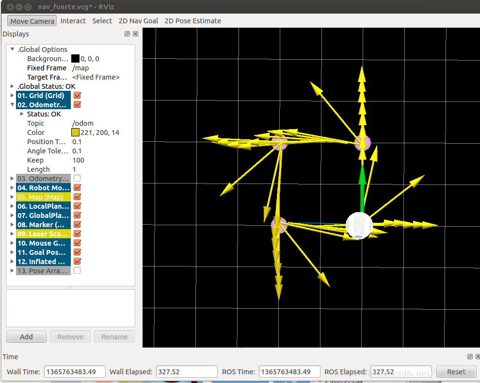
在rviz中的轨迹图如下:
在机器人移动过程中,有一条蓝色的线(被黄线挡住了)就是机器人的全局规划的路径;红色的箭头是实施规划的路线,会不断更新,有的时候会呈现很大的弧线,那是因为机器人在转向的过程中尽量希望保持平稳的角度。如果觉得路径规划的精度不够,可以修改配置文件中的pdist_scale参数进行修正。
然后我们可以认为的确定目标位置,点击rviz上方的2D Nav Goal按键,然后左键选择目标位置,机器人就开始自动导航了。
六、ArbotiX仿真——带有障碍物的路径规划
首先我们让机器人走一个正方形的路线。先通过上面的命令,让机器人回到原始位置(0,0,0),然后按reset按键,把所有的箭头清除。接着运行走正方形路径的代码:rosrun rbx1_nav move_base_square.py
在rviz中可以看到:
四个顶角的粉色圆盘就是我们设定的位置,正方形比较规则,可见定位还是比较准确的。然我们先来分析一下走正方形路线的代码:import roslib; roslib.load_manifest('rbx1_nav') from actionlib_msgs.msg import * from geometry_msgs.msg import Pose, Point, Quaternion, Twist from move_base_msgs.msg import MoveBaseAction, MoveBaseGoal from tf.transformations import quaternion_from_euler from visualization_msgs.msg import Marker from math import radians, pi rospy.init_node('nav_test', anonymous=False) rospy.on_shutdown(self.shutdown) square_size = rospy.get_param("~square_size", 1.0) euler_angles = (pi/2, pi, 3*pi/2, 0) for angle in euler_angles: q_angle = quaternion_from_euler(0, 0, angle, axes='sxyz') waypoints.append(Pose(Point(square_size, 0.0, 0.0), quaternions[0])) waypoints.append(Pose(Point(square_size, square_size, 0.0), quaternions[1])) waypoints.append(Pose(Point(0.0, square_size, 0.0), quaternions[2])) waypoints.append(Pose(Point(0.0, 0.0, 0.0), quaternions[3])) for waypoint in waypoints: self.markers.points.append(p) self.cmd_vel_pub = rospy.Publisher('cmd_vel', Twist) self.move_base = actionlib.SimpleActionClient("move_base", MoveBaseAction) rospy.loginfo("Waiting for move_base action server...") self.move_base.wait_for_server(rospy.Duration(60)) rospy.loginfo("Connected to move base server") rospy.loginfo("Starting navigation test") while i < 4 and not rospy.is_shutdown(): self.marker_pub.publish(self.markers) goal.target_pose.header.frame_id = 'map' goal.target_pose.header.stamp = rospy.Time.now() goal.target_pose.pose = waypoints[i] self.move_base.send_goal(goal) finished_within_time = self.move_base.wait_for_result(rospy.Duration(60)) if not finished_within_time: self.move_base.cancel_goal() rospy.loginfo("Timed out achieving goal") state = self.move_base.get_state() if state == GoalStatus.SUCCEEDED: rospy.loginfo("Goal succeeded!") marker_color = {'r': 1.0, 'g': 0.7, 'b': 1.0, 'a': 1.0} self.marker_pub = rospy.Publisher('waypoint_markers', Marker) self.markers.ns = marker_ns self.markers.id = marker_id self.markers.type = Marker.SPHERE_LIST self.markers.action = Marker.ADD self.markers.lifetime = rospy.Duration(marker_lifetime) self.markers.scale.x = marker_scale self.markers.scale.y = marker_scale self.markers.color.r = marker_color['r'] self.markers.color.g = marker_color['g'] self.markers.color.b = marker_color['b'] self.markers.color.a = marker_color['a'] self.markers.header.frame_id = 'map' self.markers.header.stamp = rospy.Time.now() self.markers.points = list() rospy.loginfo("Stopping the robot...") self.move_base.cancel_goal() self.cmd_vel_pub.publish(Twist()) if __name__ == '__main__': except rospy.ROSInterruptException: rospy.loginfo("Navigation test finished.")
但是,在实际情况中,往往需要让机器人自动躲避障碍物。move_base包的一个强大的功能就是可以在全局规划的过程中自动躲避障碍物,而不影响全局路径。障碍物可以是静态的(比如墙、桌子等),也可以是动态的(比如人走过)。
现在我们尝试在之前的正方形路径中加入障碍物。把之前运行fake_move_base_blank_map.launch的中断Ctrl-C掉,然后运行:roslaunch rbx1_nav fake_move_base_obstacle.launch
然后就会看到在rviz中出现了障碍物。然后在运行之前走正方形路线的代码:rosrun rbx1_nav move_base_square.py
这回我们可以看到,在全局路径规划的时候,机器人已经将障碍物绕过去了,下过如下图:
在上图中,黑色的线是障碍物,周围浅色的椭圆形是根据配置文件中的inflation_radius参数计算出来的安全缓冲区。全局规划的路径基本已经是最短路径了。在仿真的过程中也可以动态重配置那四个配置文件,修改仿真参数。
(十五)——amcl(导航与定位)在理解了move_base的基础上,我们开始机器人的定位与导航。gmaping包是用来生成地图的,需要使用实际的机器人获取激光或者深度数据,所以我们先在已有的地图上进行导航与定位的仿真。
amcl是移动机器人二维环境下的概率定位系统。它实现了自适应(或kld采样)的蒙特卡罗定位方法,其中针对已有的地图使用粒子滤波器跟踪一个机器人的姿态。
一、测试
首先运行机器人节点:
roslaunch rbx1_bringup fake_turtlebot.launch
然后运行amcl节点,使用测试地图:
roslaunch rbx1_nav fake_amcl.launch map:=test_map.yaml
可以看一下fake_amcl.launch这个文件的内容:
<arg name="map" default="test_map.yaml" /> <node name="map_server" pkg="map_server" type="map_server" args="$(find rbx1_nav)/maps/$(arg map)"/> <include file="$(find rbx1_nav)/launch/fake_move_base.launch" /> <node pkg="fake_localization" type="fake_localization" name="fake_localization" output="screen" /> <node pkg="tf" type="static_transform_publisher" name="odom_map_broadcaster" args="0 0 0 0 0 0 /odom /map 100" />
这个lanuch文件作用是加载地图,并且调用fake_move_base.launch文件打开move_base节点并加载配置文件,最后运行amcl。
然后运行rviz:
rosrun rviz rviz -d `rospack find rbx1_nav`/nav_fuerte.vcg
这时在rvoiz中就应该显示出了地图和机器人:
现在就可以通过rviz在地图上选择目标位置了,然后就会看到机器人自动规划出一条全局路径,并且导航前进:
二、自主导航
在实际应用中,我们往往希望机器人能够自主进行定位和导航,不需要认为的干预,这样才更智能化。在这一节的测试中,我们让目标点在地图中随机生成,然后机器人自动导航到达目标。
这里运行的主要文件是:fake_nav_test.launch,让我们来看一下这个文件的内容:
<param name="use_sim_time" value="false" /> <include file="$(find rbx1_bringup)/launch/fake_turtlebot.launch" /> <node name="map_server" pkg="map_server" type="map_server" args="$(find rbx1_nav)/maps/test_map.yaml"/> <node pkg="move_base" type="move_base" respawn="false" name="move_base" output="screen"> <rosparam file="$(find rbx1_nav)/config/fake/costmap_common_params.yaml" command="load" ns="global_costmap" /> <rosparam file="$(find rbx1_nav)/config/fake/costmap_common_params.yaml" command="load" ns="local_costmap" /> <rosparam file="$(find rbx1_nav)/config/fake/local_costmap_params.yaml" command="load" /> <rosparam file="$(find rbx1_nav)/config/fake/global_costmap_params.yaml" command="load" /> <rosparam file="$(find rbx1_nav)/config/fake/base_local_planner_params.yaml" command="load" /> <rosparam file="$(find rbx1_nav)/config/nav_test_params.yaml" command="load" /> <node pkg="fake_localization" type="fake_localization" name="fake_localization" output="screen" /> <node pkg="tf" type="static_transform_publisher" name="map_odom_broadcaster" args="0 0 0 0 0 0 /map /odom 100" /> <node pkg="rbx1_nav" type="nav_test.py" name="nav_test" output="screen"> <param name="rest_time" value="1" /> <param name="fake_test" value="true" />
这个lanuch的功能比较多:
(1) 加载机器人驱动
(2) 加载地图
(3) 启动move_base节点,并且加载配置文件
(4) 运行amcl节点
(5) 然后加载nav_test.py执行文件,进行随机导航
相当于是把我们之前实验中的多个lanuch文件合成了一个文件。
现在开始进行测试,先运行ROS:
roscore
然后我们运行一个监控的窗口,可以实时看到机器人发送的数据:
rxconsole
接着运行lanuch文件,并且在一个新的终端中打开rviz:
roslaunch rbx1_nav fake_nav_test.launch rosrun rviz rviz -d `rospack find rbx1_nav`/nav_test_fuerte.vcg
好了,此时就看到了机器人已经放在地图当中了。然后我们点击rviz上的“2D Pose Estimate”按键,然后左键在机器人上单击,让绿色的箭头和黄色的箭头重合,机器人就开始随机选择目标导航了:
其中包括距离信息、状态信息、目标的编号、成功率和速度等信息。
三、导航代码分析
import roslib; roslib.load_manifest('rbx1_nav') from actionlib_msgs.msg import * from geometry_msgs.msg import Pose, PoseWithCovarianceStamped, Point, Quaternion, Twist from move_base_msgs.msg import MoveBaseAction, MoveBaseGoal from random import sample from math import pow, sqrt rospy.init_node('nav_test', anonymous=True) rospy.on_shutdown(self.shutdown) self.rest_time = rospy.get_param("~rest_time", 10) self.fake_test = rospy.get_param("~fake_test", False) goal_states = ['PENDING', 'ACTIVE', 'PREEMPTED', 'SUCCEEDED', 'ABORTED', 'REJECTED', 'PREEMPTING', 'RECALLING', 'RECALLED', locations['hall_foyer'] = Pose(Point(0.643, 4.720, 0.000), Quaternion(0.000, 0.000, 0.223, 0.975)) locations['hall_kitchen'] = Pose(Point(-1.994, 4.382, 0.000), Quaternion(0.000, 0.000, -0.670, 0.743)) locations['hall_bedroom'] = Pose(Point(-3.719, 4.401, 0.000), Quaternion(0.000, 0.000, 0.733, 0.680)) locations['living_room_1'] = Pose(Point(0.720, 2.229, 0.000), Quaternion(0.000, 0.000, 0.786, 0.618)) locations['living_room_2'] = Pose(Point(1.471, 1.007, 0.000), Quaternion(0.000, 0.000, 0.480, 0.877)) locations['dining_room_1'] = Pose(Point(-0.861, -0.019, 0.000), Quaternion(0.000, 0.000, 0.892, -0.451)) self.cmd_vel_pub = rospy.Publisher('cmd_vel', Twist) self.move_base = actionlib.SimpleActionClient("move_base", MoveBaseAction) rospy.loginfo("Waiting for move_base action server...") self.move_base.wait_for_server(rospy.Duration(60)) rospy.loginfo("Connected to move base server") initial_pose = PoseWithCovarianceStamped() n_locations = len(locations) start_time = rospy.Time.now() rospy.loginfo("*** Click the 2D Pose Estimate button in RViz to set the robot's initial pose...") rospy.wait_for_message('initialpose', PoseWithCovarianceStamped) self.last_location = Pose() rospy.Subscriber('initialpose', PoseWithCovarianceStamped, self.update_initial_pose) while initial_pose.header.stamp == "": rospy.loginfo("Starting navigation test") while not rospy.is_shutdown(): sequence = sample(locations, n_locations) if sequence[0] == last_location: if initial_pose.header.stamp == "": distance = sqrt(pow(locations[location].position.x - locations[last_location].position.x, 2) + pow(locations[location].position.y - locations[last_location].position.y, 2)) rospy.loginfo("Updating current pose.") distance = sqrt(pow(locations[location].position.x - initial_pose.pose.pose.position.x, 2) + pow(locations[location].position.y - initial_pose.pose.pose.position.y, 2)) initial_pose.header.stamp = "" self.goal = MoveBaseGoal() self.goal.target_pose.pose = locations[location] self.goal.target_pose.header.frame_id = 'map' self.goal.target_pose.header.stamp = rospy.Time.now() rospy.loginfo("Going to: " + str(location)) self.move_base.send_goal(self.goal) finished_within_time = self.move_base.wait_for_result(rospy.Duration(300)) if not finished_within_time: self.move_base.cancel_goal() rospy.loginfo("Timed out achieving goal") state = self.move_base.get_state() if state == GoalStatus.SUCCEEDED: rospy.loginfo("Goal succeeded!") distance_traveled += distance rospy.loginfo("State:" + str(state)) rospy.loginfo("Goal failed with error code: " + str(goal_states[state])) running_time = rospy.Time.now() - start_time running_time = running_time.secs / 60.0 rospy.loginfo("Success so far: " + str(n_successes) + "/" + str(100 * n_successes/n_goals) + "%") rospy.loginfo("Running time: " + str(trunc(running_time, 1)) + " min Distance: " + str(trunc(distance_traveled, 1)) + " m") rospy.sleep(self.rest_time) def update_initial_pose(self, initial_pose): self.initial_pose = initial_pose rospy.loginfo("Stopping the robot...") self.move_base.cancel_goal() self.cmd_vel_pub.publish(Twist()) slen = len('%.*f' % (n, f)) return float(str(f)[:slen]) if __name__ == '__main__': except rospy.ROSInterruptException: rospy.loginfo("AMCL navigation test finished.")
(十六)——HRMRP机器人的设计1. HRMRP简介
HRMRP(Hybrid Real-time Mobile Robot Platform,混合实时移动机器人平台)机器人是我在校期间和实验室的其他小伙伴一起从零开始设计并开发的一款机器人平台,其中大部分扩展电路、驱动和ROS相关的底层功能都是我们自己做的。该机器人平台具有软硬件可编程、灵活性强、模块化、易扩展、实时性强等特点,机器人的整体结构如下图所示。 
HRMRP具备丰富的传感器和执行器,在该平台的基础上,我们设计并实现了机器人SLAM、自主导航、人脸识别、机械臂控制等功能。在设计开发完成之初,我们参加了2013年的OpenHW大赛,并且获得了全国一等奖,此外还在中国智能机器人学术会议上发表学术论文一篇,获得了会议的十佳论文奖。这个机器人陪伴我走过了研究生的三年时光,接下来的几篇博客,我会详细介绍HRMRP从设计到实现方面的很多细节。就机器人的性能来讲,很多方面是超越已有同等级的很多机器人的,但是由于我们开发能力、时间的限制,并没有在最终的应用中充分发挥他的潜力,这也给我留下了一些遗憾。 废话不多说,先让大家对该机器人有一个整体的印象:
2. HRMRP的总体架构
如下图所示,我们根据层次化、模块化的思想,设计的HRMRP的总体架构。 3. 硬件层
3.1 机械平台 HRMRP 主体结构为铝合金材质,尺寸为 316mm×313mm×342mm (高×宽×长),装配两个驱动轮与一个万向轮。驱动轮由两个 30W 的直流电机带动,转速可达 83 转/分钟,机器人最快速度 1.5m/s。HRMRP 还装有一个六自由度机械臂, 可以完成三维空间内的夹取操作。
3.2 控制平台 嵌入式系统具备小型化、低功耗、低成本、高灵活性等显著的特点, 电子技术的 发展,也促使可编程门阵列FPGA在嵌入式系统中 得到了越来越广泛的应用,很大程度上改善了嵌入式系统硬件的灵活度与繁琐计算的 实时化。 HRMRP的控制平台即基于 Xilinx 最新一代集成 FPGA 与 ARM 的片上系统 (System-on-Chip,SoC)——Zynq。 Zynq 由处理系统(Processor System, PS)与可编程逻辑(Programmable Logic, PL)两部分组成。其中 PS 基于 ARM Cortex-A9 双核处理器构建,包含常用的外设接口,例如网络、 USB、内存控制器等。而 PL 由 Xilinx 的 7 系列 FPGA 构成,支持动 态重配置,可以使用 Verilog 语言编程使用。在HRMRP 中,PS通过操作系统控制所 有功能正常有序的实现,而 PL作为协处理器一方面可以对复杂的运算并行加速处理, 另一方面可以进行 I/O 接口扩展,为多传感器和执行器设计统一的接口,提高系统硬 件配置的灵活性。 在机器人核心传感器的选择上, HRMRP使用了高性价比、高集成度的微软 Kinect 传感器。 除此还装配有超声波、加速度、里程计、陀螺仪等多种传感器, 确保机器人 平台可以采集到丰富的传感信息。
4. 驱动层
驱动层的主要工作是采集或预处理硬件层的数据,下发操作系统层的指令,为底层硬件与上层功能模块提供相应的数据传输通道。由于我们采用的“ARM+FPGA”异构控制平台,为配合硬件层硬件功能,驱动层也分为两部分,分别放置于硬件的PS端和PL端。 PS端主要驱动连接到ARM处理器的外设,例如通过PS中的OpenNI驱动 Kinect, 并且提供 PL 端到 PS 端的接口。而在PL端中,利用可编程硬件的灵活性和并行处理能力,来进行 I/O 扩展与算法的硬件加速, 如下图所示。 在I/O 扩展方面,在传统的设计实现当中,由于种类繁多的传感器、 执行器对接口的要求各不相同,会占用大量 I/O 资源,增加处理器的负担。而在HRMRP的ARM+FPGA系统当中,通过定义一组标准的硬件接口, 连接传感器和电机等外设,可使用编程逻辑取代繁杂的电路连接工作,满足各种不同需求的硬件外设。 在硬件加速方面,一般来说PS端适合常用接口的驱动、网络数据的处理等功能,而PL端适合于规律性的算法处理,在HRMRP中主要负责Kinect的数据预处理工作(这里我们将OpenNI中的部分代码放入FPGA中进行加速)。PS与PL相互配合,提高了系统数据处理的实时性。
5. 操作系统层
操作系统层是机器人平台的控制核心,集成了机器人的功能模块,负责行为控制、 数据上传、指令解析、人机交互等功能。为与 ROS 通讯接口保持一致,使用Ubuntu12.04作为操作系统,运行于Zynq的PS端ARM处理器之中。ROS为用户的不同需求提供了大小和功能不同的多种安装包,为了减少ARM端的执行压力, HRMRP编译移植了仅包括 ROS 基本通讯机制的核心库。继承了ROS的优势,机器人平台具备ROS通讯以及功能包运行的能力,与上层网络指令无缝连接,结合开源软件库,极大的丰富了机器人的功能模块与应用范围。 HRMRP是一种较为典型的高性能、低成本机器人平台。与现在研究和应用中使用较为广泛的TurtleBot、 Pioneer等机器人相比,HRMRP具有相似的结构与尺寸,同样可以完成多种多样的机器人应用,但是在接口的可扩展性、传感器的丰富度以及成本控制等方面,具备更好的综合性能。 今天就针对HRMRP的设计写到这里,下篇继续针对细节实现进行分析。
(十七)——构建完整的机器人应用系统 上一篇博客介绍了HRMRP机器人平台的设计,基于该平台,可以完成丰富的机器人应用,以较为典型的机器人导航为例,如何使用HRMRP来完成相应的功能?本篇博客将详细介绍如何将HRMRP应用到实际的应用当中。 1. 系统架构
ROS作为一个分布式框架,从微观的角度讲,分布式体现在节点的布局和配置上,而从宏观的角度来讲,这种分布式可以体现在多机器人、多主机集成的系统当中。ROS社区中针对多机器人系统并没有很多的涉及,相关应用也比较少。在HRMRP机器人的基础上,我们试图去提出一种多机器人实现的框架,如下图所示:
2. Server (服务器) 由于机器人架构多种多样,处理应用的能力也各不相同,在不同场合下的需求也有差异,我们设计了服务器层来提高机器人应用的计算能力,负责调度、分配多机器人应用中的任务,同时为用户提供友好、易用的人机交互界面。 分布的机器人节点与服务器都采用ROS框架设计,使用无线网络通讯,可以快速集成ROS社区中丰富的应用功能。在多机器人系统当中,通过机器人之间的信息共享和与任务协作,可以让每个机器人在充分发挥自己的能力的同时,获得更多额外的应用潜力。 3. Robot Node(机器人节点) 机器人节点是应用的执行者与信息的采集者。在该系统中可以集成多种采用ROS框架的机器人,这里以我们设计的HRMRP机器人平台为例,上一篇博客中已经进行了详细的介绍。
4. 机器人导航 HRMRP机器人平台采用嵌入式系统作为主控,对于机器人导航等复杂算法的处理能力有限,于是我们将应用的处理在服务器端实现,机器人将采集到的周围环境信息和自身传感器信息发布,由服务器订阅消息并完成处理和显示,再向下发布控制指令。 数据的处理流程如下: SLAM的效果如下: 5. 多机器人实验
当然,该系统对多机器人的支持也是很好的,由于时间有限,我们只做了一个简单的机器人跟随实验。该实验使用了两个机器人,除HRMRP机器人之外,还使用树莓派制作了一个简单的小型机器人。在实验中,HRMRP机器人在地图上自主导航前进,服务器负责应用的处理与显示,同时将HRMRP的位置信息转发给树莓派机器人,树莓派机器人收到信息后,紧跟HRMRP。 实验效果如下: 6.相关论文
(十八)——重读tf在之前的博客中,有讲解tf的相关内容,本篇博客重新整理了tf的介绍和学习内容,对tf的认识会更加系统。
1 tf简介1.1 什么是tf tf是一个让用户随时间跟踪多个参考系的功能包,它使用一种树型数据结构,根据时间缓冲并维护多个参考系之间的坐标变换关系,可以帮助用户在任意时间,将点、向量等数据的坐标,在两个参考系中完成坐标变换。 tf的相关设计思想,可以参见:tf设计
1.2 tf可以做什么 一个机器人系统通常有很多三维的参考系,而且会随着时间的推移发生变化,例如全局参考系(world frame),机器人中心参考系(base frame),机械夹参考系(gripper frame),机器人头参考系(head frame)等等。tf可以以时间为轴,跟踪这些参考系(默认是10秒之内的),并且允许用户提出如下的申请: - 五秒钟之前,机器人头参考系相对于全局参考系的关系是什么样的?
- 机器人夹取的物体相对于机器人中心参考系的位置在哪里?
- 机器人中心参考系相对于全局参考系的位置在哪里?
tf可以在分布式系统中进行操作,也就是说一个机器人系统中所有的参考系变换关系,对于所有节点组件,都是可用的,所有订阅tf消息的节点都会缓冲一份所有参考系的变换关系数据,所以这种结构不需要中心服务器来存储任何数据。
1.3 tf的使用流程 想要使用tf功能包,总体来讲可以分为以下两个步骤: (1) 监听tf变换 接收并缓存系统中发布的所有参考系变换,并从中查询所需要的参考系变换。 (2) 广播tf变换 向系统中广播参考系之间的坐标变换关系。系统中更可能会存在多个不同部分的tf变换广播,每个广播都可以直接将参考系变换关系直接插入tf树中,不需要再进行同步。
2 tf实例理解
3 tf基础教程
4 tf功能包的API说明5 命令行工具 虽然tf是ROS中的一个代码链接库,但是仍然提供了丰富的命令行工具来帮助用户调试和创建tf变换。
5.1 tf_monitor tf_monitor工具的功能是打印tf树中的所有参考系信息,通过输入参数来查看指定参考系之间的信息。 命令格式如下: - tf_monitor
- tf_monitor <source_frame> <target_target>
示例结果如下图所示:
5.2 tf_echo tf_echo工具的功能是查看指定参考系之间的变换关系。 命令的格式如下: - tf_echo <source_frame> <target_frame>
示例效果如下图所示:
5.3 static_transform_publisher static_transform_publisher工具的功能是发布两个参考系之间的静态坐标变换,两个参考系一般不发生相对位置变化。 命令的格式如下: - static_transform_publisher x y z yaw pitch roll frame_id child_frame_id period_in_ms
- static_transform_publisher x y z qx qy qz qw frame_id child_frame_id period_in_ms
以上两种命令格式,需要设置坐标的偏移和旋转参数,偏移参数都使用相对于xyz三轴的坐标位移,而旋转参数第一种命令格式使用以弧度为单位的 yaw/pitch/roll三个角度(yaw是围绕x轴旋转的偏航角,pitch是围绕y轴旋转的俯仰角,roll是围绕z轴旋转的翻滚角),而第二种命令格式使用四元数表达旋转角度。发布频率以ms为单位,一般100ms比较合适。 该命令不仅可以在终端中使用,还可以在launch文件中使用,使用方式如下: <node pkg="tf" type="static_transform_publisher" name="link1_broadcaster" args="1 0 0 0 0 0 1 link1_parent link1 100" />
5.4 view_frames view_frames 是可视化的调试工具,可以生成pdf文件,来显示整棵tf树的信息。 命令行的执行方式如下: roswtf是ROS中自查的工具,也可以作为组件使用。针对tf,roswtf可以检查tf的配置并发现常见问题。 命令的使用方式如下:
|


